Rules
Overview
Rules determine state changes based on an input signal. Each rule has logic to evaluate each new signal value to determine if a state has changed for the rule.
For example, a threshold type rule could evaluate if a value is now above a warning level and when detected create a warning state change event, going from Normal, OK Warning.
---
config:
  theme: neutral
---
graph LR
  Signal@{ shape: das, label: "Signal" }
  d0@{ shape: framed-circle, label: "Data Point" }
  d1@{ shape: framed-circle, label: "Data Point" }
  d2@{ shape: framed-circle, label: "Data Point" }
  d3@{ shape: sm-circ, label: "Data Point" }
  Rule{Rule};
  style Rule stroke-width:3px
  DPC@{ shape: brace-r, label: "New Incoming Signal Values" }
  EVENTC@{ shape: brace-l, label: "State Change Detected: Warning Level" }
  DPC ~~~ d0
  d0 e1@-.- d1 e2@-.- d2 e3@-.- Signal e4@-.- d3 e5@--> Rule
  %%d3 eTS@-.-o ts
  state_change@{ shape: f-circ }
  style state_change fill:#fdd835,stroke:#fdd835
  Rule e6@-.- | State<br>Change | state_change
  state_change ~~~ EVENTC
  e1@{ animate: true }
  e2@{ animate: true }
  e3@{ animate: true }
  e4@{ animate: true }
  e5@{ animate: true }
  e6@{ animate: true }
Configuration
Rules are configured as a part of the Asset's signal data pipeline, always attached to a signal. The Asset Configuration allows editing the parameters / constants for the rule. Rules are a part of a templated asset and inherit the parameters from the template. (Note: Optional functionally allows overriding rule constants for assets linked to a template.) Solutions may implement solution level custom rules. (Note: Only the built-in threshold rules allow for displaying thresholds on dashboard panels.)
Signals technically may have multiple rules associated with them to look for different types of conditions (operational state, timeout, etc) and/or use different types of logic. Overall the rule states provide the current status for the specific signal and contribute to the overall status for an asset.
It's important to note that a single rule, like the off the shelf Threshold rule (more info below), can look for multiple threshold state level criteria and do not require separate rules. The most typical second rule is the off the shelf Timeout rule to look for a situation where the signal has not reported a value for some amount of time and would indicate a connection problem.
---
config:
  theme: neutral
---
graph LR
  Signal@{ shape: das, label: "Signal" }
  d0@{ shape: f-circ, label: "Data Point" }
  d1@{ shape: f-circ, label: "Data Point" }
  d2@{ shape: f-circ, label: "Data Point" }
  d3@{ shape: f-circ, label: "Data Point" }
  style d0 fill:#DDD,stroke:#999,fill-opacity:0.1,stroke-dasharray:2
  style d1 fill:#DDD,stroke:#999,fill-opacity:0.1,stroke-dasharray:2
  style d2 fill:#DDD,stroke:#999,fill-opacity:0.1,stroke-dasharray:2
  style d3 fill:#DDD,stroke:#999,fill-opacity:0.1,stroke-dasharray:2
  Rule{Threshold Rule};
  RuleTimeout{Timeout Rule};
  DPC@{ shape: brace-r, label: "No new values.<br>Showing expected rate" }
  EVENTC@{ shape: brace-l, label: "State Change Detected: Timeout" }
  DPC ~~~ d0
  d0 ~~~ d1 ~~~ d2 ~~~ Signal -.- d3 -.- Rule
  d3 -.- RuleTimeout
  state_change@{ shape: f-circ }
  style state_change fill:#999,stroke:#999
  RuleTimeout e6@-.- | State<br>Change | state_change
  state_change ~~~ EVENTC
  e6@{ animate: true }
Rule Logic
Rules are signal data event driven in that they run on each signal data point as soon as it enters the data pipeline (e.g. Sensor reading -> Device Channel -> Asset Signal -> Rule function). These functions, being event driven, evaluate the new value and return a decision on whether there is a state change based on previous last state of the rule.
ExoSense includes several off the shelf rules (documented below) that have logic for common use cases like numeric thresholds, a contains check for string values, a boolean check, an is equal to numeric check, signal timeouts and repeating values. The ExoSense pipeline's rule functionality includes built-in support for sustained values such as over a time period, a count, or a count in a time period.
The off the shelf Timeout rule has extra built-in logic to 'timeout' when the rule has not received a new signal value for a specified amount of time. This timeout rule creates a special category of status that allows Timeout status to be showing on signals and assets.
Debouncing
Real-world sensor signals are rarely clean. A temperature reading may briefly spike above a threshold and recover, a vibration sensor may oscillate around a setpoint, and a string status value may flicker between states while a device is transitioning. Without debouncing, every qualifying value triggers a state change event — generating noise for operators, flooding notification channels, and obscuring genuine conditions.
ExoSense's standard rules address this with two complementary mechanisms that can be used independently or together:
Duration
Duration options require a condition to be sustained before a state change is triggered. This filters out momentary spikes or brief matches that do not represent a real condition.
| Duration Type | How it debounces |
|---|---|
| Once | No debouncing — triggers immediately on each qualifying value. Use when every value change is meaningful. |
| Sustained Duration | Condition must hold continuously for a configured time period before triggering. |
| Repeated | Condition must be true for a consecutive count of incoming values before triggering. |
| Repeated Over Time | Condition must be true a configured number of times within a time window before triggering. |
Hysteresis (Threshold rule only)
Hysteresis prevents oscillation at a threshold boundary by creating a dead-band: after a state becomes active, the signal must cross a separate offset threshold before the state clears. Where Duration filters entry noise, Hysteresis filters exit noise — once active, the value must recover meaningfully before the rule resets.
Used together, Duration controls when a state is entered and Hysteresis controls when it exits, giving full resilience against signals that are noisy on approach and slow to recover.
Checks
Checks functionality runs before a Rule function's logic to "check" to see if a signal (the calling signal or any other) meets a criteria or if there is a specific time window to run / not run the rule. For more details: Rule & Transform Checks
Out of Order Data Filtering
Out of Order Data Filtering is used to filter out signal values that have a timestamp before the last processed signal value's timestamp to prevent incorrect realtime rule state events from being generated and incorrect statuses on signals and assets.
Rule logic to determine new status does not go back into time. This situation may occur when signal sources like IoT devices use recorded data (i.e. provide their own timestamps with values) and are sending data out of historical order - such as first in, last out situations. See below about recorded data handling for more information on impact to rules. This option is enabled by default on new rules and is recommended. Legacy assets and asset templates may be disabled.
Recording Historical Data and Rules
Data that is recorded with historical timestamps (i.e. backfilling) using Device record functionality should take into consideration the order of data and the impacts on the event drive pipeline rules.
- Use the
Out of Order Data Filteringoption which will stop the rule from processing data values with timestamps before the last value (compared to wall clock), preventing incorrect status events and notifications from being generated. - Signals that are typically backfilled historically or may not keep track of timestamp ordering may not want to use rules, it may not make sense. Consider filtering with Transforms and/or visualization of data along with post processing analytics and use of the
Out of Order Data Filteringoption. - If you must backfill data and/or send data with a recorded timestamp while using Rules to trigger state change events, ensure the edge device firmware sends in chronological timestamp order.
Rule Actions
When a rule detects a new state, there are a number of outcomes and additional triggered activities.
Rule State Change Activities:
- Event Log - An event is recorded to the asset event log
- Status - The rule's status changes (which is used in the UI and API calls)
- Notifications - Notifications based on user subscriptions are sent out.
- Conditions - The condition service evaluates whether to create a new Condition based on the policy associated to the rule. (Advanced Feature)
- Actions - Action functions that have been connected to this rule will be triggered. (Advanced Feature)
The Using Rules Guide provides a step by step walk through of using rules in ExoSense.
---
config:
  theme: neutral
---
graph LR
  Signal@{ shape: das, label: "Signal" }
  d3@{ shape: sm-circ, label: "Data Point" }
  Rule{Rule};
  style Rule stroke-width:3px
  EventLog@{ shape: cyl, label: "Event Log<br>History" }
  Signal e4@-.- d3 e5@--> Rule
  state_change@{ shape: f-circ }
  style state_change fill:#fdd835,stroke:#fdd835,fill-opacity:0.4;
  Rule e6@-.- | State<br>Change | state_change
  state_change e7@--> EventLog ~~~ ELC@{ shape: brace-l, label: "The state change information including level (e.g. Warning), is recorded." }
  Rule --- Status@{ shape: curv-trap, label: "Updated Rule State: <br>OK -> Warning"} ~~~ SC@{ shape: brace-l, label: "Visualizations / API will use this state when evaluating Signal & Asset Statuses." }
  style Status fill:#fdd835,stroke:#fdd835,fill-opacity:0.2
  state_change e9@--> Notify@{ shape: subproc, label: "Notification<br>Subscriptions"}
  state_change e10@--> Conditions@{ shape: subproc, label: "Condition<br>Management"}
  Conditions ~~~ CC@{ shape: brace-l, label: "If Condition Policies are in use, check to see if new condition exists." }
  state_change e11@--> Actions@{ shape: procs, label: "Action Functions"}
  Actions ~~~ AC@{ shape: brace-l, label: "Triggers any Action functions attached to Rule" }
  Notify--> Email["Email"]
  Notify--> SMS["SMS"]
  e4@{ animate: false }
  e5@{ animate: false }
  e6@{ animate: true }
  e7@{ animate: true }
  %%e8@{ animate: true }
  e9@{ animate: true }
  e10@{ animate: true }
  e11@{ animate: true }
Rule Condition States
Severity States
Rules generate status events which are logged in the Asset Log and affect the connected Signals status and the overall Asset Status. In the application, Critical status (shown as red) takes preference over Warning status (yellow), which takes preference over OK status (green).
| Event Status (Severity) | System Color | Status Precedence | General Description |
|---|---|---|---|
Ok | None | Event state associated as being normal or good. | |
Warning | > Ok | Event State used by some rules for noting that a signal state is not normal or close too bad. This should be monitored appropriately or preemptive action taken. | |
Critical | > Warning | Event State used by some rules for noting that a signal state is bad and action should be taken immediately. | |
Error | > Critical | There is an issue with the signal or rule that prevents the rule from actually determining the current state. Action is recommended. | |
Informational | None | Event State used by some rules to provide information but is not associated as good or bad. |
Quick Summary on 'Statuses'
- Precedence: Severity Ordering: Normal < Warning < Critical < Error
- Timeout: Other rule statuses will be available to see, but since we do not have new data this only provides indication of what the last state was before the timeout. Address why the signal is in Timeout as other rules are not longer getting data
- Informational: Is only informational, does not have any severity indication.
For more details: Asset and Signal Statuses
Timeout States
Timeout states for signals are handled separately. Any signal that has a timeout rule associated to it, will roll up to the overall Asset. If the signal is timed out, the asset will show a timeout icon throughout the application. Timeout states do not change the last known signal status. Dashboard panels that show signals will indicate when a specific signal is timed out.
| Event Status | Precedence | General Description |
|---|---|---|
Timeout | A timeout assumes we only know last state of signal. | The rule for the signal has detected that no value has been received past a given timeout period and therefore is in a timeout state. |
Not In Timeout | None | The rule for the signal has detected that the last value has been received within a given period and therefore is not in a timeout state. |
Notifications Messages
Rule status events are recorded to an Asset's event log. In addition, notifications are sent out based on a user's notification preference and subscriptions set up in their profile.
Rules may support additional custom messages that can be included in notifications. Each rule function supports this individually. The text entered in these fields is included in the notification messages sent out to users.
Notifications and Message Formats
Standard Rules
Standard Rules are the built-in rule types included with every ExoSense application. They cover the most common signal monitoring patterns — numeric thresholds, string matching, boolean state, exact value equality, data timeout, and repeating data detection — and require no custom code to configure.
Common Parameters
All standard rules share the following parameters:
| Parameter | Description |
|---|---|
| Name | The rule name used in the asset configuration view. |
| Message when no condition matches | Prefix text applied to Event messages (Log, Notifications) when no condition is currently active. Applies to rules that support multiple match conditions per rule (Threshold, Contains). |
Threshold (Numeric type)
The Threshold rule is the most commonly used rule in ExoSense and is designed for numeric signals. It evaluates each incoming signal value against one or more user-defined threshold conditions (e.g. > 75, < 10) and generates a state change event when a condition is met or cleared. Each threshold condition has its own severity level (Warning or Critical), allowing a single rule to represent multiple alert tiers for the same signal.
Key capabilities:
- Multiple thresholds per rule — define separate Warning and Critical levels without needing multiple rules.
- Hysteresis — prevents rapid state toggling ("flapping") by requiring the value to move past an offset before entering or leaving the active state. Can be used with or without Duration Options.
- Duration options — require the condition to be sustained for a time period, a count of consecutive values, or a count within a time window before triggering, reducing false positives from momentary spikes. Duration options are only applied entering a state, not exiting and can be used with or without Hysteresis.
- Dashboard visualization — threshold levels can be displayed as refer ence lines on dashboard panels (unique to the built-in Threshold rule).
Each threshold level within the rule has its own set of parameters:
| Parameter | Required? | Description |
|---|---|---|
| Operation | Required | The logical operator for the comparison: >, >=, <, <=, =, ≠. |
| Threshold Value | Required | The numeric value the signal is compared against. |
| Hysteresis Enter | Required | Offsets the entry threshold in the triggering direction — the signal must cross the shifted boundary before the active state is entered. Defaults to 0 (entry triggers at value exactly). |
| Hysteresis Exit | Required | Offsets the exit threshold in the clearing direction — the signal must cross the shifted boundary before the active state is cleared. Defaults to 0 (exit at the strict inverse of entry). |
| Duration Type | Required | How long or how many times the condition must be true before triggering a state change. Defaults to Sustained Duration — see below. |
| Message when threshold matches | Optional | Prefix text applied to Event messages (Log, Notifications) when this threshold condition is active. |
Threshold Logic
Each operator defines both an entry condition (when the state becomes active) and an exit condition (when it clears).
With both Hysteresis values at 0, the exit is the strict inverse of the entry.
When non-zero, Hysteresis Enter (H_e) shifts the entry threshold — the signal must move further past the boundary before triggering. Hysteresis Exit (H_x) shifts the exit threshold in the clearing direction, creating a dead-band the signal must fully cross before the state clears.
| Operation | State becomes active when | State clears when |
|---|---|---|
A > threshold | A > threshold | A <= threshold |
A >= threshold | A >= threshold | A < threshold |
A < threshold | A < threshold | A >= threshold |
A <= threshold | A <= threshold | A > threshold |
A = threshold | A = threshold | A ≠ threshold |
A ≠ threshold | A ≠ threshold | A = threshold |
| Operation | State becomes active when | State clears when |
|---|---|---|
A > threshold | A > threshold + H_e | A <= threshold - H_x |
A >= threshold | A >= threshold + H_e | A < threshold - H_x |
A < threshold | A < threshold - H_e | A >= threshold + H_x |
A <= threshold | A <= threshold - H_e | A > threshold + H_x |
A = threshold | |A − threshold| ≤ H_e | |A − threshold| > H_e |
A ≠ threshold | |A − threshold| > H_e | |A − threshold| ≤ H_e |
For = and ≠, H_e acts as a symmetric tolerance window around threshold. H_x has no effect on either operator.
Hysteresis
Understanding Hysteresis
Hysteresis requires the signal to move a defined offset past the threshold before the active state is cleared.
Example: threshold > 75 (Warning) with Hysteresis 1.2 — the value must drop below 73.8 to return to Normal.
Enter / Exit behavior

Hysteresis with Count

Flapping vs Hysteresis

Choosing Between Hysteresis and Duration/Count
Both approaches reduce false positives but solve different problems. They can also be combined.
| Approach | How it works | Best for |
|---|---|---|
| Hysteresis | Shifts the exit threshold by an offset — state entry is immediate, exit is delayed until the value moves far enough away | Signals that hover or oscillate right at the threshold boundary |
| Duration / Count | Requires the condition to hold for a time period or consecutive count before entering the active state — adds entry latency | Noisy signals with short-lived spikes that should not trigger a state change |
| Both combined | Duration/Count governs how long the condition must be true to enter; Hysteresis governs how far the value must recover before exiting | Highest stability — filters out entry noise and prevents premature exit once active |
Duration Options
Once
Evaluates only the most recent signal value. A state change occurs immediately when the condition becomes true or false.

Sustained Duration (Default)
The condition must remain continuously true for a specified Duration before triggering a state change. Any value that breaks the condition resets the timer.

Repeated
The condition must be true for a consecutive Count of incoming values. Any value that breaks the condition resets the count.

Repeated Over Time
The condition must be true a specified Count of times within a Duration window to trigger a state change.

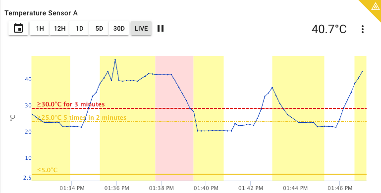
Example showing duration state changes on dashboard panel
Contains (String type)
The Contains rule is used with String signal types to watch for the presence of a specific substring within the signal's value. It performs a case-sensitive substring search and supports multiple match conditions in a single rule, each with its own alert level.
Common use cases include monitoring status strings returned by a device (e.g. "fault", "error", "ok") and generating different severity events based on which substring is found.
String Normalization
Strings are normalized using NFC (Canonical Decomposition, followed by Canonical Composition) before comparison. See Unicode Normalization Forms for details.
Each match condition within the rule has its own set of parameters:
| Parameter | Required? | Description |
|---|---|---|
| Substring to match | Required | The string to search for within the signal's current value. The check is case-sensitive. |
| Alert level | Required | The severity level (Warning, Critical, or Informational) assigned when this substring is found. |
| Duration Type | Required | How long or how many times the match must hold before triggering a state change. Defaults to Once — see below. |
| Message when match is found | Optional | Prefix text applied to Event messages (Log, Notifications) when this match condition is active. |
Duration Options
Once (Default)
Evaluates only the most recent signal value. A state change occurs immediately when the substring is found or no longer found.

Sustained Duration
The substring match must remain true for a specified Duration before triggering a state change. Any value that breaks the match resets the timer.

Repeated
The substring match must be true for a consecutive Count of incoming values. Any non-matching value resets the count.

Repeated Over Time
The substring match must be true a specified Count of times within a Duration window to trigger a state change.

Boolean (Boolean type)
The Boolean rule evaluates a Boolean signal type and assigns a severity level to each state (true and false). It is the simplest rule type and is used when a signal directly represents an on/off, open/closed, or pass/fail condition where either state has defined meaning.
Parameters
| Parameter | Required? | Description |
|---|---|---|
Alert level for true | Required | The severity level (OK, Warning, Critical, or Informational) assigned when the signal value is true. |
Alert level for false | Required | The severity level assigned when the signal value is false. |
| Duration Type | Required | How long or how many times the value must hold before triggering a state change. Defaults to Once — see below. |
| Message when true | Optional | Prefix text applied to Event messages (Log, Notifications) when the value is true. |
| Message when false | Optional | Prefix text applied to Event messages (Log, Notifications) when the value is false. |
Duration Options
Once (Default)
Evaluates only the most recent signal value. A state change occurs immediately when the value changes.

Sustained Duration
The value must remain the same for a specified Duration before triggering a state change. Any change in value resets the timer.

Repeated
The value must be the same for a consecutive Count of incoming values. Any change resets the count.

Repeated Over Time
The same value must appear a specified Count of times within a Duration window to trigger a state change.

Is Equal To (Numeric type)
The Is Equal To rule checks whether a numeric signal's value exactly matches a configured value and assigns a severity level on match. Unlike the Threshold rule which evaluates ranges, this rule triggers only on an exact match (to a configurable number of decimal places) and clears as soon as the value changes. Multiple match values can be configured in a single rule, each with its own alert level.
Common use cases include monitoring device status codes or mode values where specific numeric codes represent known conditions (e.g. error code 3 = Critical, mode 0 = Informational).
Parameters
| Parameter | Required? | Description |
|---|---|---|
| Value to compare to | Required | The numeric value the signal must equal to trigger this match. |
| Decimal places | Required | The number of decimal places used in the comparison. Defaults to 1. |
| Alert level when equal | Required | The severity level (Warning, Critical, or Informational) assigned when the signal equals this value. |
| Duration Type | Required | How long or how many times the match must hold before triggering a state change. Defaults to Once — see below. |
| Message when equal | Optional | Prefix text applied to Event messages (Log, Notifications) when the match is active. |
| Message when not equal | Optional | Prefix text applied to Event messages (Log, Notifications) when the match is no longer active. |
Duration Options
Once (Default)
Evaluates only the most recent signal value. A state change occurs immediately when the value matches or stops matching.

Sustained Duration
The match must remain true for a specified Duration before triggering a state change. Any value that breaks the match resets the timer.

Repeated
The match must be true for a consecutive Count of incoming values. Any non-matching value resets the count.

Repeated Over Time
The match must be true a specified Count of times within a Duration window to trigger a state change.

Timeout
The Timeout rule monitors whether a signal is still receiving data. If no new value is received within a configured interval, the signal enters a timeout state. Any new value immediately exits the timeout. Both transitions — entering and exiting — generate an event in the asset log and can trigger notifications.
Unlike other rules which evaluate signal values, the Timeout rule evaluates time since last value. It is independent of the signal's current value and does not change the signal's Warning or Critical status — it adds a separate Timeout indicator visible throughout the application.

Enabling the Timeout Features
The timeout Rule and visualization of timeout status in ExoSense are controlled a Feature Flag switch found on the Configuration page's Features tab. Note: Dashboard Panels can visualize a timeout using only the signal's timeout property. Timeout rules are not required for showing individual signal timeouts on dashboard panels.
Asset Timeout Rule - Makes the Timeout Rule available in the asset configuration
Asset Timeout Visualization and Alerts
An asset will be shown in asset lists, group view, and maps with a timeout indicator if any signal that has a timeout rule is in the timeout state. Only one signal needs a timeout rule for this to occur. For application use cases where all signals are sourced from a single device, only one timeout rule is typically necessary.
Parameters
| Parameter | Required? | Description |
|---|---|---|
| Timeout Interval | Required | The maximum time without a new value before entering the timeout state. Specified in minutes or hours. Minimum is 1 minute. |
| Message when timed out | Optional | Prefix text applied to Event messages (Log, Notifications) when entering the timeout state. |
| Message when timed in | Optional | Prefix text applied to Event messages (Log, Notifications) when exiting the timeout state. |
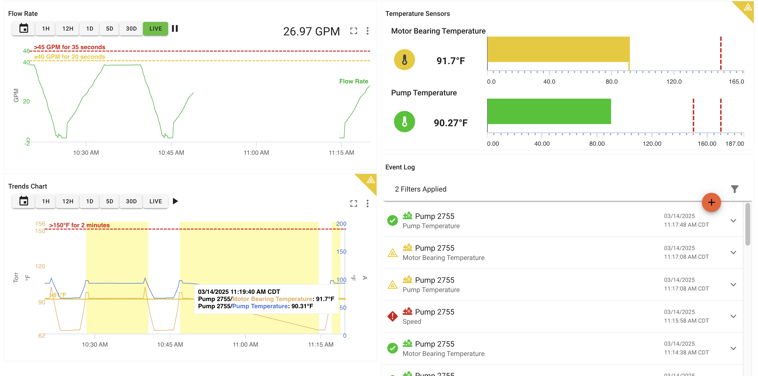
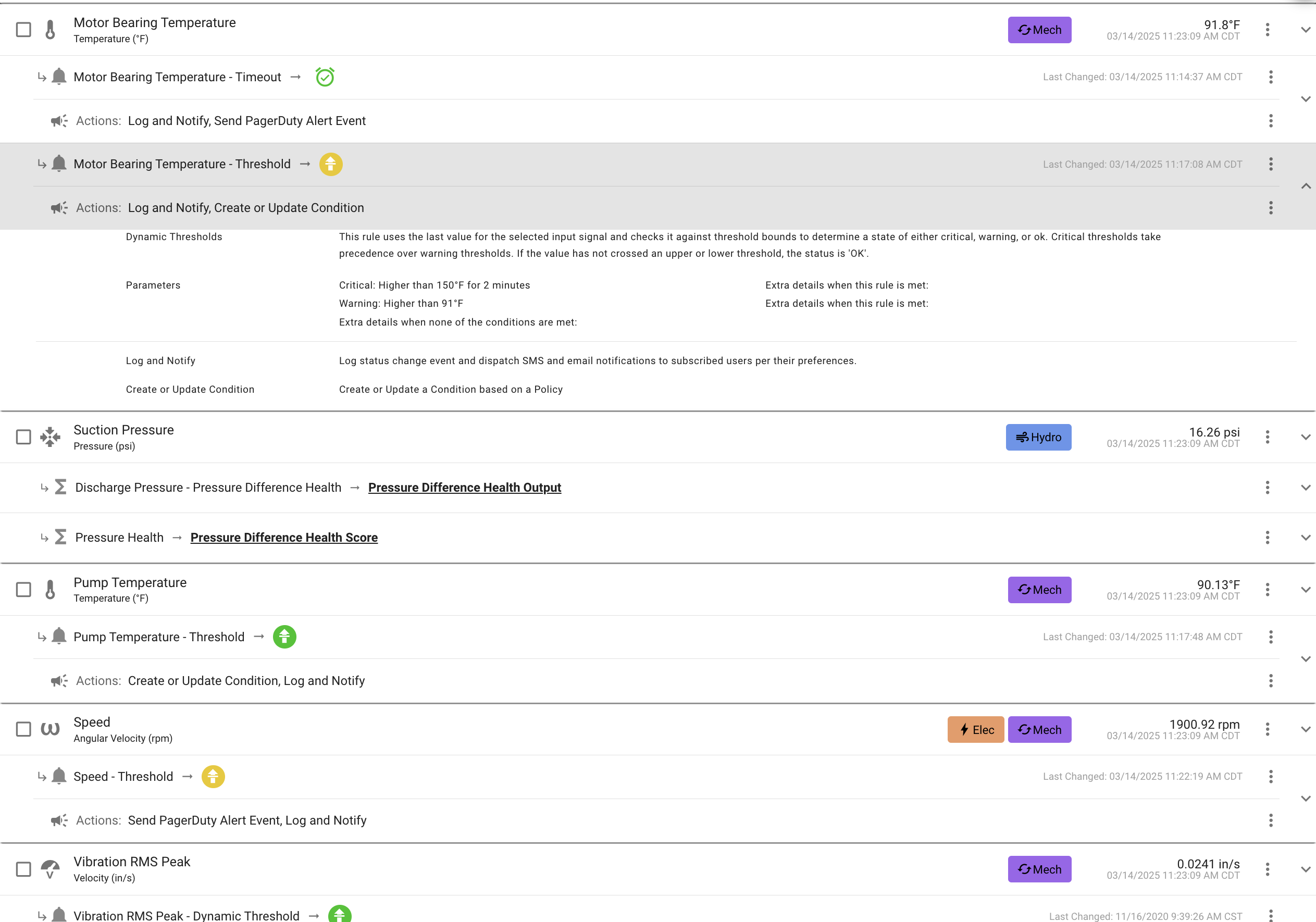
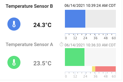
A signal with both a timeout rule (shown in timeout state) and a threshold rule. 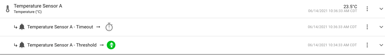
Timeout Rule vs Signal Timeout Property
The dashboard panels will use a Timeout Rule for showing a signal's timeout status. If none is found, it will use the Signal's Timeout property if it exists to show a timeout state. A signal timeout property is only visual, it does not generate a timeout event / notification.
Repeating Value
The Repeating Value rule detects when a signal is sending the same value repeatedly — an indication that the source device or firmware may be stuck or frozen. Unlike the Threshold rule which watches for a value crossing a boundary, this rule watches for a lack of change.
Common use cases include detecting a sensor that has stopped updating (but is still connected and reporting), a stuck actuator feedback signal, or a firmware bug causing repeated identical transmissions.
The Repeating Value rule complements the Timeout rule. Timeout detects when data stops arriving; Repeating Value detects when data arrives but never changes.
Parameters
| Parameter | Required? | Description |
|---|---|---|
| Decimal places | Required | The number of decimal places used when comparing values. Defaults to 1. |
| Alert level | Required | The severity level (Warning or Critical) assigned when the repeat condition is met. |
| Duration Type | Required | How long or how many times the same value must repeat before triggering. Defaults to Repeated with a count of 5. |
Duration Options
Once
Not recommended — triggers immediately on the first value regardless of repetition, which defeats the purpose of this rule.
Sustained Duration
The same value must be received continuously for a specified Duration before triggering.

Repeated (Default)
The same value must be received for a consecutive Count of incoming values before triggering.

Repeated Over Time
The same value must appear a specified Count of times within a Duration window to trigger.

Other Rules
ExoSense instances may have other rules added by administrators, built specifically for the instance or added from the IoT Marketplace. These rules will have their own descriptions, input and outputs, and constants.